物联网年-连接2行LCD显示器(译文)
By robot-v1.0
本文链接 https://www.kyfws.com/pi/the-year-of-iot-hooking-up-a-2-line-lcd-display-zh/
版权声明 本博客所有文章除特别声明外,均采用 BY-NC-SA 许可协议。转载请注明出处!
- 18 分钟阅读 - 8669 个词 阅读量 0物联网年-连接2行LCD显示器(译文)
原文地址:https://www.codeproject.com/Articles/1274259/The-Year-of-IoT-Hooking-Up-a-2-Line-LCD-Display
原文作者:Marc Clifton
译文由本站 robot-v1.0 翻译
前言
The journey of using .NET Core to send text to a 2 line LCD connected to an rPi
使用.NET Core将文本发送到连接到rPi的2行LCD的过程
内容(Contents)
介绍(Introduction)
与纯软件有所不同,我还想了解.NET Core控制硬件的能力,在这种情况下,使用I2C接口.这使我陷入了很多兔子洞和死胡同,最初发现了三个提供必要解决方案的职位:(Taking a break from pure software, I am also interested in checking out .NET Core’s capabilities to control hardware, in this case using the I2C interface. This led me down a lot of rabbit holes and dead ends, initially finding three posts that provided the necessary solution:)
- 第30课I2C LCD1602-C代码示例(Lesson 30 I2C LCD1602 - C code example)
- 使用.NET Core 2从使用Ubuntu 16.04连接到Raspberry Pi 3的I2C设备进行读取(Using .NET Core 2 to read from an I2C device connected to a Raspberry Pi 3 with Ubuntu 16.04)
- Debian Jessie与C#.Net Core的I2C通信(Debian Jessie I2C Communication With C# .Net Core)
#2似乎是从#3衍生而来的,但省略了(#2 seems to have been derived from #3, but left out the)
writeP/调用声明.奇怪的是,我找不到在C#中使用LCD1602的任何示例-为了使此工作正常进行,有必要将C代码移植到C#(琐碎),并对幕后发生的情况做出一些猜测- -那(P/Invoke declaration. Odd that I couldn’t find any examples of using the LCD1602 in C# – to get this working, it was necessary to port the C code to C# (trivial) and make a couple guesses as to what was going on behind the scenes – that)wiringPiI2CWrite(fd, temp);调用C代码.我偶然发现了"(call in the C code. I’ve stumbled across “)wiringpi“之前-他们的网站似乎已经停工,但是有(” before – their website seems to be defunct but there are) GitHub上的6个仓库(6 repos in GitHub) 支持C,Python,PHP,Ruby,Perl和Node.但是没有C#.(supporting C, Python, PHP, Ruby, Perl, and Node. But no C#.) 在显示器上找到实际的数据表也需要花费大量的时间,这对于理解所有写操作来控制显示器确实是必不可少的-对于博客文章,使用通过带有rPi的LCD1602(或其他Arduino的SBC),我发现了对硬件制造商和型号的引用,并通过C ++代码中的一些注释生成了数据手册PDF!(It also took a good amount of sleuthing to find the actual datasheet on the display which is really necessary to understand what all the bit writes are doing to control the display – it’s a rather sad state of affairs that of the blog posts on using the LCD1602 with the rPi (or other SBC’s like an Arduino), I found a reference to the hardware manufacturer and model, which led to the datasheet PDF, via some comments in C++ code!)
步骤0:获得带有I2C搭载模块的LCD1602(Step 0: Obtain an LCD1602 with I2C Piggyback Module)
我买了(I bought) Freenove的Raspberry Pi终极入门套件(Freenove’s Ultimate Starter Kit for Raspberry Pi) 几天后到达时感到惊喜.打包好的东西包,其中大部分我还没有探索过,并且下载了非常不错的PDF文件,包括项目,硬件数据表以及GitHub存储库的链接.令我惊讶的是,LCD1602已经装配了I2C接口,这很棒,因为我最初打算使用(and was pleasantly surprised when it arrived a few days later. Very packed package of goodies, most of which I haven’t explored yet, and a very decent download of PDFs including projects, hardware datasheets, and the link to the GitHub repo. And to my surprise, the LCD1602 had already been assembled with an I2C interface which was great because I had originally intended to use the) 格罗夫液晶显示器(Grove LCD) :(:)
因为它支持I2C接口(白色连接器),并且我有一对夫妇是由一位客户提供的(我承认我最初购买Freenove的套件只是为了连接电线,哈哈哈.)我在LCD1602上看到的文章使用了GPIO线,我并不热衷于创建接线混乱:(because it supported an I2C interface (the white connector) and I had a couple lying around courtesy of a client (I confess I bought Freenove’s kit initially just for the hookup wires, hahaha.) The articles I’d seen on the LCD1602 used the GPIO lines and I wasn’t keen on creating a wiring mess:)

(图片来自((image from) Sunfounder第13课LCD1602(Sunfounder Lesson 13 LCD1602) )())
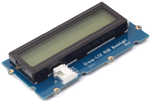
相反,Freenove套件中的LCD1602具有漂亮整洁的I2C:(Instead, the LCD1602 in Freenove’s kit has a nice and tidy I2C:)
(图片来自((image from) 创办人我(Sunfounder I)2(2)液晶显示器(C LCD1602) )()) 连接起来更加整洁,快捷!(Much neater and faster to hook up!)
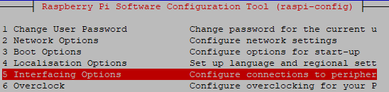
步骤1:启用I2C(Step 1: Enable I2C)
就像我上一篇文章一样,我们必须使用(As in my last article, we have to use) sudo raspi-config 启用I2C.选择 “(to enable the I2C. Select “)界面选项(Interface Options)":(":)
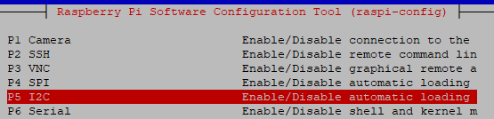
然后选择I2C:(Then select I2C:)
然后选择(and select)是(Yes)提示:(to the prompt:)

退出配置应用程序,然后(Exit out of the configuration app and)重启你的rPi(reboot your rPi).我忘记了这一步,所以起初事情对我来说不太好!(. I’d forgotten that step and so things didn’t work too well for me at first!)
步骤2:连接LCD1602(Step 2: Wire Up the LCD1602)
显然(我希望)是在rPi掉电(电源线物理断开的情况下)上进行的.您可以阅读有关I2C接口的信息.(Obviously (I hope), do this with the rPi powered off (the power cable physically disconnected.) You can read about the I2C interface) 这里(here) :(:)
I2C是用于两线接口的串行协议,用于连接低速设备,例如微控制器,EEPROM,A/D和D/A转换器,I/O接口以及嵌入式系统中的其他类似外设.它是由飞利浦发明的,现在几乎所有主要的IC制造商都在使用它.(I2C is a serial protocol for two-wire interface to connect low-speed devices like microcontrollers, EEPROMs, A/D and D/A converters, I/O interfaces and other similar peripherals in embedded systems. It was invented by Philips and now it is used by almost all major IC manufacturers.)
通常,只有一个主设备(rPi),并且可以将几乎无限数量的从设备连接到总线(我想主要是受地址可用性的限制-有些设备使用多个地址.)电源仅需要四根电线,地面,时钟和数据.许多I2C器件使用3.3V电源供电(或工作在3.3V至5V范围内),但对于LCD1602,则需要将其连接至5V电源.接线图(There is typically one master (the rPi) and an almost unlimited number of slave devices can be attached to the bus (limited I would imagine mainly by address availability – some devices use multiple addresses.) There are only four wires required for power, ground, clock, and data. Many I2C devices work off of the 3.3V supply (or work in the range from 3.3V to 5V) but in the case of the LCD1602, it needs to be hooked up to the 5V supply. A wiring diagram from) 这里(here) :(:)
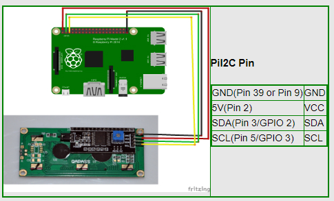
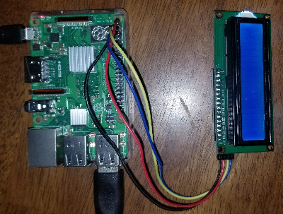
和我的实现(我将引脚9接地):(And my implementation (I used pin 9 for ground):)
步骤3:验证可以找到设备(Step 3: Verify Device Can Be Found)
执行以下命令:(Execute this command:)
i2cdetect -y -r 1
并且您应该看到:(and you should see:)
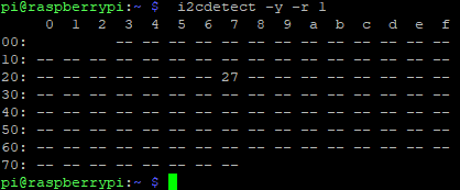
请注意”(Note the “) 27 “-这表示已检测到默认地址为0x27的LCD1602.如果在此位置仅看到破折号,请重新检查接线.(” - this indicates that the LCD1602, which by default is at address 0x27, has been detected. If you see only dashes in this position, recheck your wiring.)
步骤4:代码(Step 4: The Code)
通过合并引言中提到的三篇文章中的内容,我得到了此代码,该代码已进行了重构,以最终处理多个设备(请注意,尽管我尚未使用多个I2C设备进行测试!),多个文件句柄.我将解释” …"((By merging the pieces from the three articles mentioned in the introduction, I arrived at this code, which has been refactored a bit to handle eventually working with multiple devices (note though that I haven’t tested this with multiple I2C devices!), requiring multiple file handles. I’ll explain what is in the “…” () enum 定义).(definitions) in a bit.)
using System.Runtime.InteropServices;

namespace consoleApp
{
  public class I2C
  {
    ...

    private static int OPEN_READ_WRITE = 2;

    [DllImport("libc.so.6", EntryPoint = "open")]
    public static extern int Open(string fileName, int mode);

    [DllImport("libc.so.6", EntryPoint = "close")]
    public static extern int Close(int handle);

    [DllImport("libc.so.6", EntryPoint = "ioctl", SetLastError = true)]
    private extern static int Ioctl(int handle, int request, int data);

    [DllImport("libc.so.6", EntryPoint = "read", SetLastError = true)]
    internal static extern int Read(int handle, byte[] data, int length);

    [DllImport("libc.so.6", EntryPoint = "write", SetLastError = true)]
    internal static extern int Write(int handle, byte[] data, int length);

    private int handle = -1;

    public void OpenDevice(string file, int address)
    {
      // From: https://stackoverflow.com/a/41187358
      // The I2C slave address set by the I2C_SLAVE ioctl() is stored in an i2c_client
      // that is allocated everytime /dev/i2c-X is opened. So this information is local
      // to each "opening" of /dev/i2c-X.
      handle = Open("/dev/i2c-1", OPEN_READ_WRITE);
      var deviceReturnCode = Ioctl(handle, (int)IOCTL_COMMAND.I2C_SLAVE, address);
  }

    public void CloseDevice()
    {
      Close(handle);
      handle = -1;
    }

    protected void WriteByte(byte data)
    {
      byte[] bdata = new byte[] { data };
      Write(handle, bdata, bdata.Length);
    }
  }
}
初始化并写入LCD1602的类:(And the class that initializes and writes to the LCD1602:)
using System.Text;
using System.Threading;

namespace consoleApp
{
  public class Lcd1602 : I2C
  {
    ... (more enums, explained below)

    protected void SendCommand(int comm)
    {
      byte buf;
      // Send bit7-4 firstly
      buf = (byte)(comm & 0xF0);
      buf |= 0x04; // RS = 0, RW = 0, EN = 1
      buf |= 0x08;
      WriteByte(buf);
      Thread.Sleep(2);
      buf &= 0xFB; // Make EN = 0
      buf |= 0x08;
      WriteByte(buf);

      // Send bit3-0 secondly
      buf = (byte)((comm & 0x0F) << 4);
      buf |= 0x04; // RS = 0, RW = 0, EN = 1
      WriteByte(buf);
      Thread.Sleep(2);
      buf &= 0xFB; // Make EN = 0
      WriteByte(buf);
    }

    protected void SendData(int data)
    {
      byte buf;
      // Send bit7-4 firstly
      buf = (byte)(data & 0xF0);
      buf |= 0x05; // RS = 1, RW = 0, EN = 1
      buf |= 0x08;
      WriteByte(buf);
      Thread.Sleep(2);
      buf &= 0xFB; // Make EN = 0
      buf |= 0x08;
      WriteByte(buf);

      // Send bit3-0 secondly
      buf = (byte)((data & 0x0F) << 4);
      buf |= 0x05; // RS = 1, RW = 0, EN = 1
      buf |= 0x08;
      WriteByte(buf);
      Thread.Sleep(2);
      buf &= 0xFB; // Make EN = 0
      buf |= 0x08;
      WriteByte(buf);
    }

    public void Init()
    {
      SendCommand(0x33); // Must initialize to 8-line mode at first
      Thread.Sleep(2);
      SendCommand(0x32); // Then initialize to 4-line mode
      Thread.Sleep(2);
      SendCommand(0x28); // 2 Lines & 5*7 dots
      Thread.Sleep(2);
      SendCommand(0x0C); // Enable display without cursor
      Thread.Sleep(2);
      SendCommand(0x01); // Clear Screen
    }

    public void Clear()
    {
      SendCommand(0x01); //clear Screen
    }

    public void Write(int x, int y, string str)
    {
      // Move cursor
      int addr = 0x80 + 0x40 * y + x;
      SendCommand(addr);

      byte[] charData = Encoding.ASCII.GetBytes(str);

      foreach (byte b in charData)
      {
        SendData(b);
      }
    }
  }
}
要使用此代码向LCD1602写入消息,我们现在可以调用以下测试方法:(To use this code to write a message to the LCD1602, we can now call this test method:)
static void Main(string[] args)
{
  Console.WriteLine("Testing 1602");
  Test1602();
}

static void Test1602()
{
  Lcd1602 lcd = new Lcd1602();
  lcd.OpenDevice("/dev/i2c-1", LCD1602_ADDRESS);
  lcd.Init();
  lcd.Clear();
  lcd.Write(0, 0, "Hello");
  lcd.Write(0, 1, "     World!");
  lcd.CloseDevice();
}
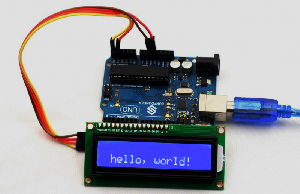
在发布并SCP加载到rPi之后,当我们运行(After publishing and SCP’ing to the rPi, when we run) consoleApp ,它显示:(, it displays:)

到底发生了什么?(What’s Really Going On?)
上面的代码很好,但实际上是怎么回事,特别是LCD1602类中所有这些不可思议的位是什么?(The above code is all fine and good, but what is really going on, and in particular, what are all these magic bits that are being or’ed and and’ed in the LCD1602 class?)
I2C基础(I2C Basics)
经过一番挖掘,我发现(After some digging, I found) 这个回购(this repo) 其中包含许多其他文件:(which contains, among many other files:)
- i2c_dev.h(i2c_dev.h)
这描述了什么是神奇的0x07 …数字,我已经在其中进行了编码(This described what the magic 0x07… numbers are, which I’ve recoded in)
enums,保留来自(s, preserving the comments from the)**.H(.h)**文件:(file:)
// From: https://github.com/spotify/linux/blob/master/include/linux/i2c-dev.h
private enum IOCTL_COMMAND
{
  /* /dev/i2c-X ioctl commands. The ioctl's parameter is always an
  * unsigned long, except for:
  * - I2C_FUNCS, takes pointer to an unsigned long
  * - I2C_RDWR, takes pointer to struct i2c_rdwr_ioctl_data
  * - I2C_SMBUS, takes pointer to struct i2c_smbus_ioctl_data
  */

  // number of times a device address should be polled when not acknowledging
  I2C_RETRIES = 0x0701,

  // set timeout in units of 10 ms
  I2C_TIMEOUT = 0x0702,

  // Use this slave address
  I2C_SLAVE = 0x0703,

  // 0 for 7 bit addrs, != 0 for 10 bit
  I2C_TENBIT = 0x0704,

  // Get the adapter functionality mask
  I2C_FUNCS = 0x0705,

  // Use this slave address, even if it is already in use by a driver!
  I2C_SLAVE_FORCE = 0x0706,

  // Combined R/W transfer (one STOP only)
  I2C_RDWR = 0x0707,

  // != 0 to use PEC with SMBus
  I2C_PEC = 0x0708,

  // SMBus transfer
  I2C_SMBUS = 0x0720,
}
我并不是真的了解所有这些选项的作用,但至少对它们有什么解释(Not that I actually understand what all these options are and do, but at least there is some explanation of what they)意思(mean).另外,请注意(. Also, note that the)**.H(.h)**文件将来可能对(file will probably be useful in the future for) I2C_SMSBUS 和(and) I2C_RDWR 控制函数,在这里以C形式显示:(control functions, which I show here in their C form:)
/* This is the structure as used in the I2C_SMBUS ioctl call */
struct i2c_smbus_ioctl_data {
  __u8 read_write;
  __u8 command;
  __u32 size;
  union i2c_smbus_data __user *data;
};

/* This is the structure as used in the I2C_RDWR ioctl call */
  struct i2c_rdwr_ioctl_data {
  struct i2c_msg __user *msgs; /* pointers to i2c_msgs */
  __u32 nmsgs; /* number of i2c_msgs */
};
写入LCD1602 I2C(Writing to the LCD1602 I2C)
为了更详细地了解所有这些不可思议的作用,我最终回顾了C ++中的C ++代码.(To understand in more detail what all these magic bits are doing, I ended up reviewing the C++ code in the) Arduino液晶I2C库(Arduino Liquid Crystal I2C Library) ,尤其是:(, particularly:)
- .cpp文件(The .cpp file)
- .h文件(The .h file)
的(The)**.H(.h)**文件特别定义了各种位常量,我将其重新编码为C#(file in particular defines a variety of bit constants which I’ve recoded as C#)
enums:(:)
// Source for enums:
// https://github.com/fdebrabander/Arduino-LiquidCrystal-I2C-library/blob/master/LiquidCrystal_I2C.h
// commands
private enum Commands
{
  LCD_CLEARDISPLAY = 0x01,
  LCD_RETURNHOME = 0x02,
  LCD_ENTRYMODESET = 0x04,
  LCD_DISPLAYCONTROL = 0x08,
  LCD_CURSORSHIFT = 0x10,
  LCD_FUNCTIONSET = 0x20,
  LCD_SETCGRAMADDR = 0x40,
  LCD_SETDDRAMADDR = 0x80,
}

// flags for display entry mode
private enum DisplayEntryMode
{
  LCD_ENTRYRIGHT = 0x00,
  LCD_ENTRYLEFT = 0x02,
  LCD_ENTRYSHIFTINCREMENT = 0x01,
  LCD_ENTRYSHIFTDECREMENT = 0x00,
}

// flags for display on/off control
private enum DisplayControl
{
  LCD_DISPLAYON = 0x04,
  LCD_DISPLAYOFF = 0x00,
  LCD_CURSORON = 0x02,
  LCD_CURSOROFF = 0x00,
  LCD_BLINKON = 0x01,
  LCD_BLINKOFF = 0x00,
}

// flags for display/cursor shift
private enum DisplayCursorShift
{
  LCD_DISPLAYMOVE = 0x08,
  LCD_CURSORMOVE = 0x00,
  LCD_MOVERIGHT = 0x04,
  LCD_MOVELEFT = 0x00,
}

// flags for function set
private enum FunctionSet
{
  LCD_8BITMODE = 0x10,
  LCD_4BITMODE = 0x00,
  LCD_2LINE = 0x08,
  LCD_1LINE = 0x00,
  LCD_5x10DOTS = 0x04,
  LCD_5x8DOTS = 0x00,
}

// flags for backlight control
private enum BacklightControl
{
  LCD_BACKLIGHT = 0x08,
  LCD_NOBACKLIGHT = 0x00,
}

private enum ControlBits
{
  En = 0x04, // Enable bit
  Rw = 0x02, // Read/Write bit
  Rs = 0x01 // Register select bit
}
在里面(In the)**.cpp(.cpp)**文件,我发现了这个宝石:(file, I found this gem:)
// put the LCD into 4 bit mode
// this is according to the hitachi HD44780 datasheet
// figure 24, pg 46
奇怪的是看到一个仅带有注释的代码块,不是吗.但是,它向我指出了Hitachi HD44780数据表.谷歌(Odd to see a code block that has just comments, isn’t it. However, it pointed me to the Hitachi HD44780 datasheet. Google that,) 这是一个链接(here’s a link) 到许多具有可下载PDF的站点.最后!到底发生了什么的真正"来源”.例如,查看初始化显示的C ++代码:(to one site of many having a downloadable PDF. Finally! The real “source” for what is going on. For example, looking at the C++ code that initializes the display:)
// we start in 8bit mode, try to set 4 bit mode
write4bits(0x03 << 4);
delayMicroseconds(4500); // wait min 4.1ms

// second try
write4bits(0x03 << 4);
delayMicroseconds(4500); // wait min 4.1ms

// third go!
write4bits(0x03 << 4);
delayMicroseconds(150);

// finally, set to 4-bit interface
write4bits(0x02 << 4);
这对应于我发现的C#代码:(This corresponds to the C# code that I’d found:)
SendCommand(0x33); // Must initialize to 8-line mode at first
Thread.Sleep(2);
SendCommand(0x32); // Then initialize to 4-line mode
此处的区别在于,每个半字节都被发送,因此写入0x33和0x32对应于写入0x03\0x03\0x03和0x02的C ++代码.(The difference here is that each nybble is being sent, hence writing 0x33 and 0x32 corresponds to the C++ code that writes 0x03, 0x03, 0x03, and 0x02.)
这对应于数据表中描述初始化工作流程的文档:(This corresponds to the documentation in datasheet that describes the initialization workflow:)
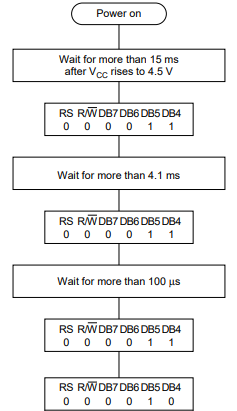
但是,它仍然没有解释这些不可思议的位,也没有解释为什么每4位发生2次写入,例如,此片段写入了命令的4个最高有效(MSB)位:(But it still doesn’t explain these magic bits and why 2 writes occur for each 4 bits, for example, this fragment which writes the 4 most significant (MSB) bits of command:)
// Send bit7-4 firstly
buf = (byte)(comm & 0xF0);
buf |= 0x04; // RS = 0, RW = 0, EN = 1
buf |= 0x08;
WriteByte(buf);
Thread.Sleep(2);
buf &= 0xFB; // Make EN = 0
buf |= 0x08;
WriteByte(buf);
我还想了解为什么将设备置于4位模式而不是将其置于8位模式.(I also want to understand why the device is put into 4 bit mode as opposed to leaving it in 8 bit mode.)
在数据表的第22页中,我们读取:(In the datasheet, page 22, we read: “)在两次传输4位数据之后,HD44780U和MPU之间的数据传输完成.(The data transfer between the HD44780U and the MPU is completed after the 4-bit data has been transferred twice.)“让我们看看(” Let’s look at the) write C ++代码中的函数:(functions in the C++ code:)
void LiquidCrystal_I2C::write4bits(uint8_t value) {
  expanderWrite(value);
  pulseEnable(value);
}

void LiquidCrystal_I2C::expanderWrite(uint8_t _data){
  Wire.beginTransmission(_addr);
  Wire.write((int)(_data) | _backlightval);
  Wire.endTransmission();
}

void LiquidCrystal_I2C::pulseEnable(uint8_t _data){
  expanderWrite(_data | En); // En high
  delayMicroseconds(1); // enable pulse must be >450ns

  expanderWrite(_data & ~En); // En low
  delayMicroseconds(50); // commands need > 37us to settle
}
此代码特别奇怪,因为(This code is particularly odd because the) write4bits 正在打电话(is calling) expanderWrite 3次!我想知道这是否是代码中的错误.(3 times! I wonder if that’s a bug in the code.)
因此,在此代码中,我们看到,根据数据表,每个半字节都发送两次,一次为Enable,第二次为Enable.这由位2控制(我们总是从0开始计数):(So we see in this code that, as per the datasheet, each nybble is being sent twice, once with the Enable high, the second time with the Enable low. This is controlled by bit 2 (we always count from 0):) En = 0x04, // Enable bit .此外,显示始终设置为”(. Furthermore, the display is always set to “) on 在编写命令时,由位3控制:(” when writing a command, controlled by bit 3:) LCD_BACKLIGHT = 0x08 .如果在编写"命令"时不执行此操作,则在向显示器写入文本时显示器"闪烁”(变黑),因为首先必须发送命令(如果未设置位3,则显示器变暗),然后设置第3位并打开显示屏的文本.(. If we don’t do this when writing a “command”, the display “flashes” (it turns dark) when writing text to the display because first the command has to be sent (if bit 3 is not set, the display goes dark), then the text, which sets bit 3 and turns on the display.)
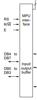
不幸的是,数据表中没有描述"在高四位中的命令/数据,而在低位中显示+使能+读/写+寄存器选择"!经过一番认真的挖掘,我遇到了(Unfortunately, none of this “command/data in the upper four bits, and display + enable + read/write + register select in the lower bits”, is described in the datasheet! After some serious digging, I came across) 这个连结(this link) 表示:“有两种方法可以使用I2C将LCD连接到Raspberry Pi.最简单的方法是将LCD与I2C背包连接起来.最核心的DIY方法是使用标准的HD44780 LCD并将其连接到Pi通过称为PCF8574的芯片.“啊哈!我们现在可以看一下(that stated: “There are a couple ways to use I2C to connect an LCD to the Raspberry Pi. The simplest is to get an LCD with an I2C backpack. The hardcore DIY way is to use a standard HD44780 LCD and connect it to the Pi via a chip called the PCF8574.” Ah ha! We can now look at the) PCF8574数据表(datasheet for the PCF8574) !此外,终于让我意识到LCD1602进入4位模式的原因是因为必须将4位用作数据,而将3位用作LCD1602的使能(E),寄存器选择(RS)的控制. )和读/写(R/〜W)行,如下所示(LCD1602数据表的第3页):(! Furthermore, it finally dawns on me that the reason the LCD1602 is put into 4 bit mode is because 4 bits have to be used as the data and 3 bits need to be used as control of the LCD1602’s enable (E), register select (RS) and read/write (R/~W) lines, as shown here (page 3 of the datasheet for the LCD1602):)
解释了位0\1和2:(That explains bits 0, 1 and 2:)
private enum ControlBits
{
  En = 0x04, // Enable bit
  Rw = 0x02, // Read/Write bit
  Rs = 0x01 // Register select bit
}
但是还有两个问题:(but two questions remain:)
- 它在LCD1602数据表中说必须为每个低位切换允许线:(Where does it say in the LCD1602 datasheet that the enable line has to be toggled for each nybble: “)…在4位数据传输两次之后”.(…after the 4-bit data has been transferred twice”.)
- 当我们发送命令或数据时,位3(0x08)在做什么?显然,这可以控制显示器的开/关!(What is bit 3 (0x08) doing when we send a command or data? This is clearly controlling the display on/off!) 第21页:(Page 21:) “(")对于4位接口数据,仅使用四个总线线路(DB4至DB7)进行传输.总线DB0到DB3被禁用.在两次传输4位数据之后,HD44780U和MPU之间的数据传输完成.(For 4-bit interface data, only four bus lines (DB4 to DB7) are used for transfer. Bus lines DB0 to DB3 are disabled. The data transfer between the HD44780U and the MPU is completed after the 4-bit data has been transferred twice.)"(")
解决了位3(0x08)的奥秘(The Mystery of Bit 3 (0x08) Solved)
第二个问题第一.我一直在设置此位,因为来自(The second question first. I’ve been setting this bit because of this C code from) 第30课I2C LCD1602-C代码示例(Lesson 30 I2C LCD1602 - C code example) :(:)
int LCDAddr = 0x27;
int BLEN = 1;
int fd;

void write_word(int data){
  int temp = data;
  if ( BLEN == 1 )
    temp |= 0x08;
  else
    temp &= 0xF7;
  wiringPiI2CWrite(fd, temp);
}
什么是BLEN,为什么将其设置为1?最后,我找到了想要的东西(What is BLEN and why is it set to 1? And finally, I find what I’m looking for) 这里(here) :(:) int BLEN = 0;//1--open backlight.0--close backlight 带有以下硬件连接图(我添加了红线):(with the following hardware connection diagram (I added the red lines):)
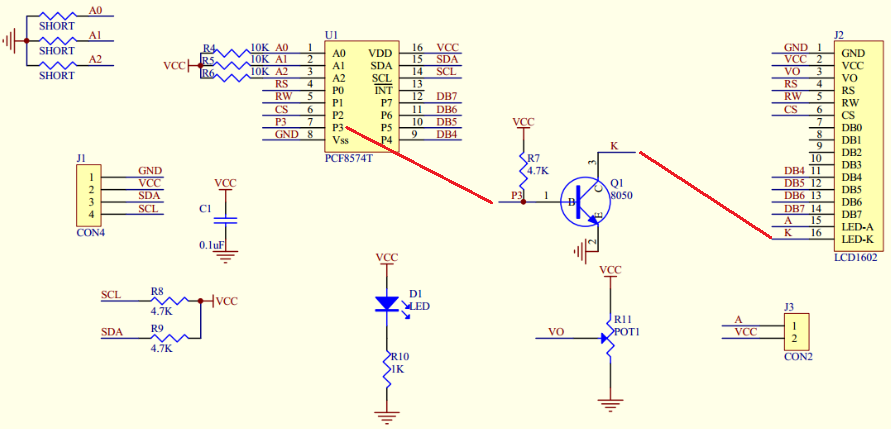
请注意,PCF8574上的P3连接到控制K的晶体管Q1的基极,K必须控制背光电压!如果P3为1,则K接地.这是从另一个验证(Note that P3 on the PCF8574 is wired to the base of transistor Q1 which controls K, which must control the backlight voltage! If P3 is 1, K grounds. This is verified from yet another) 谷歌查找(Google find) :(:)
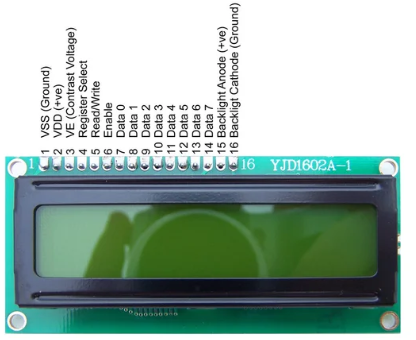
以及相关的文本:(and the associated text:) *15. BLA-背光阳极(+)(15. BLA - Backlight Anode (+)) 16. BLK-背光阴极(-)(16. BLK - Backlight Cathode (-))
最后两个引脚(15和16)是可选的,仅在显示器有背光时才使用.(The last 2 pins (15 & 16) are optional and are only used if the display has a backlight.)*
如果背光灯未接地,则不会点亮.疯.此外,如果8位数据字节,我们还将看到前3个LSB如何映射到使能,寄存器选择和R/〜W线:(*If the backlight isn’t grounded, then it isn’t illuminated. Crazy. Furthermore, we also see how the first 3 LSBs if the 8 bit data byte are mapped to the enable, register select, and R/~W lines:*)

解决了以4位模式写入时切换P2的奥秘(The Mystery of Toggling P2 When Writing in 4-bit Mode Solved)
称为” CS”(片选)的P2(0x04)是LCD1602上的"使能"引脚6.回到LCD1602数据表,我们看到使能(E)引脚开始了读/写操作:(P2 (0x04) called “CS” (chip select) is the “Enable” pin 6 on the LCD1602. Going back to the LCD1602 datasheet, we see that the enable (E) pin starts the read/write operation:)

此外,让我们从第22页的LCD1602数据表中查看该时序图:(Furthermore, let’s look at this timing diagram from the LCD1602 datasheet, page 22:)
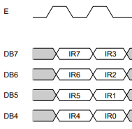
注意,启用线必须在两个半字节之间切换.唯一的方法是写"东西"(任何东西都应该做),将位2设置为0,以使线路变低.因此,现在我们可以理解为什么每个半字节必须写两次.了解这一点,我遇到的所有代码示例都可以简化为:(Notice that the enable line must be toggled between the two nybbles. The only way to do this is to write “something” (anything should do) with bit 2 set to 0 to bring the line low. So now we can understand why the each nybble has to be written twice. Understanding this, all the code examples I’ve come across can be simplified to this:)
byte buf;
// Send bit7-4 firstly
buf = (byte)(comm & 0xF0);
buf |= 0x04; // RS = 0, RW = 0, EN = 1
buf |= 0x08;
WriteByte(buf);
Thread.Sleep(2);
WriteByte(8);   // <<< === Set EN = 0, keep the display on, we don't care what the data is.

// Send bit3-0 secondly
buf = (byte)((comm & 0x0F) << 4);
buf |= 0x04; // RS = 0, RW = 0, EN = 1
buf |= 0x08;
WriteByte(buf);
Thread.Sleep(2);
WriteByte(8);	// <<< === Set EN = 0, keep the display on, we don't care what the data is.
最后! (我说的很多话.Google至少花了8个小时的时间才能找到我引用的各种链接,以便将所有内容组合在一起!)(Finally! (I’m saying that a lot. It’s taken at least 8 hours of Googling to find the various links I’ve referenced to put all the pieces together!))
现在使用各种清理代码(Now to clean the code up with the various) enum 常数:(constants:)
byte buf;
// Send bit7-4 firstly
buf = (byte)(comm & 0xF0);
buf |= (byte)ControlBits.En | (byte)BacklightControl.LCD_BACKLIGHT;
WriteByte(buf);
Thread.Sleep(2);
WriteByte((byte)BacklightControl.LCD_BACKLIGHT);

// Send bit3-0 secondly
buf = (byte)((comm & 0x0F) << 4);
buf |= (byte)ControlBits.En | (byte)BacklightControl.LCD_BACKLIGHT;
WriteByte(buf);
Thread.Sleep(2);
WriteByte((byte)BacklightControl.LCD_BACKLIGHT);
命令和数据(Commands and Data)
使用此键(LCD1602数据表的第23页):(Using this key (page 23 of the LCD1602 datasheet):)
Function set:
DL = 1; 8-bit interface data
N = 0; 1-line display
F = 0; 5 � 8 dot character font

Display on/off control:
D = 0; Display off
C = 0; Cursor off
B = 0; Blinking off

Entry mode set:
I/D = 1; Increment by 1
S = 0; No shift
现在,我们可以了解可以发送给LCD1602的命令(第6页,表6):(we can now understand the commands we can send to the LCD1602 (table 6, page 24):)
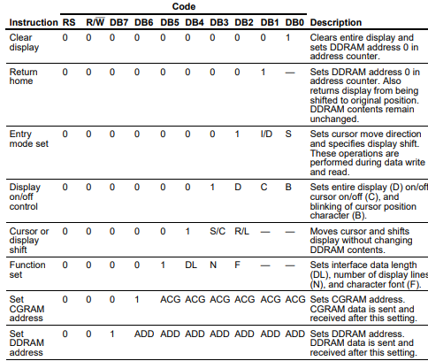
因此,例如,写入显示器(DDRAM)的RS线为低电平,而位7(0x80)始终为高电平:(So, for example, writing to the display (the DDRAM) has the RS line low and bit 7 (0x80) is always high:)
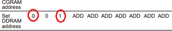
其中第一行从地址0开始,第二行从地址0x40开始:(where the first line starts at address 0 and the second line starts at address 0x40:)

对应于代码(which corresponds to the code) int addr = 0x80 + 0x40 * y + x;
通过查看表6同样可以确定其他命令(上图).是的,在这一点上,我(Other commands are determined similarly by reviewing table 6 (image above.) And yes, at this point, I’m)*做完了(done)*有了这些东西,我就让读者有足够的了解来探索所有命令.我是(with this stuff, so I leave it to the reader to have enough understanding to explore all the commands. And I am)*不(not)*将会弄清楚如何对字符集进行编程!(going to figure out how to program the character set!)
结论(Conclusion)
关于本文的奇怪之处在于,使代码正常工作需要花费数小时的时间来研究和整理各个部分.(The odd thing about this article is that getting the code to work took a couple hours of digging around and putting the pieces together.)*理解(Understanding)*代码的工作时间是原来的4倍.但这很值得,因为我现在对如何使用I2C接口和阅读未来设备的硬件图有了深刻的了解.(how the code works took 4 times as long. But it was well worth the journey as I now have a solid understanding of how to use the I2C interface and read hardware diagrams for future devices.)
许可
本文以及所有相关的源代码和文件均已获得The Code Project Open License (CPOL)的许可。
C# Raspberry .NET-Core .NET 新闻 翻译