Commodore 64仿真器(译文)
By robot-v1.0
本文链接 https://www.kyfws.com/emulation/commodore-emulator-zh/
版权声明 本博客所有文章除特别声明外,均采用 BY-NC-SA 许可协议。转载请注明出处!
- 32 分钟阅读 - 15679 个词 阅读量 0Commodore 64仿真器(译文)
原文地址:https://www.codeproject.com/Articles/795037/Commodore-Emulator
原文作者:Mladen Janković
译文由本站 robot-v1.0 翻译
前言
Another implementation of Commodore 64 emulator written in C#
用C#编写的Commodore 64仿真器的另一种实现
- 下载Commodore 64 Emulator Binaries-65.6 KB(Download Commodore 64 Emulator Binaries - 65.6 KB)
- 下载Commodore 64源代码-102.3 KB(Download Commodore 64 source Code - 102.3 KB)

背景(Background)
本文介绍有关用C#编写的Commodore 64仿真器的实现的详细信息.(This article describes details about implementation of Commodore 64 emulator written in C#.)
由于几种原因,性能不是那么好,例如基于周期的驱动器和实际驱动器仿真,以及某些在源代码中实现的方式.我出于其他目的在C ++中重新实现了仿真器,该实现大大提高了性能.在获得这些结果之后,我放弃了C#实现.由于不以某种方式使用可用的代码会浪费时间和精力,因此我决定写一篇有关该主题的文章.(The performances are not that great, because of several reasons, like cycle-based and real drive emulation as well as the way some things are implemented in source code. I re-implemented the emulator in C++ for other purposes and the implementation yielded a great increase of performance. In the wake of these results I abandoned the C# implementation. Since it would be a waste time and effort not to use the code available in some way, I decide to write an article about the subject.)
不幸的是,有些东西将仍然不完整,缺失或正确实现,但是它仍然是解释仿真基本概念的良好基础.(Unfortunately there are stuffs that will remain incomplete, missing or implemented correctly, but it is still a good base to explain the basic concept of emulation.)
在本文中,我不会尝试解释实际硬件的工作方式.有很多很棒的资源可以更好地涵盖这些主题.相反,我将注意力集中在仿真上-在此实现中应该做什么以及如何完成.(In this article I will not try to explain how the actual hardware works. There is a huge amount of great resources that cover these subjects better that I could do. Instead I will focus my attention on emulation - what should be done and how it was done in this implementation.)
在尝试构建解决方案或运行仿真器之前,您应该阅读(Before you try to build the solution or run the emulator you should read) 关于ROM文件的部分(section about ROM files) .(.)
介绍(Introduction)
Commodore 64的可见且可由程序员使用的部分是:(Parts of Commodore 64 that are visible and can be used by the programmer are:)
- 6510芯片-CPU(与6502芯片相同,但带有一个额外的IO端口)(6510 chip - the CPU (same as 6502 chip but with one additional IO port))
- VIC-II芯片-负责图形处理(VIC-II chip - responsible for graphic)
- SID芯片-负责音频(SID chip -responsible from audio)
- 2xCIA芯片-负责计时器和IO(例如串行总线,键盘,操纵杆…)(2xCIA chips - responsible for timers and IO (like serial bus, keyboard, joystick…))
- 彩色RAM-VIC-II芯片用于生成显示图形颜色的4位存储器(Color RAM - 4-bit memory used by VIC-II chip to generate colors of displayed graphic)
- RAM芯片-可供编程的64 KB(RAM chips - 64 kilobytes available to program)
- 3x ROM芯片-存储VIC-II芯片使用的基本解释器,OS(内核)和字符生成器(3xROM chips - storing Basic interpreter, OS (KERNAL) and character generator used by VIC-II chip) 该实现涵盖了运行游戏所需的大多数硬件.缺少的一件事是SID芯片仿真. REU和磁带仿真也不可用.使用适当的工具,应该可以将T64格式的可用游戏转换为D64(磁盘)格式,因此这些游戏也应该可以玩.(The implementation covers the most of the hardware needed to run games. The one major thing that is missing is SID chip emulation. REU and tape emulation is also not available. With appropriate tools it should be possible to convert games that are available in T64 format to D64 (disk) format, so those games should be playable too.)
仿真器是基于周期的,它可以完美地仿真芯片时序,并在系统中的不同芯片之间实现同步.它还实现了1541-II驱动器的真实驱动器仿真.所有这些技术都提供了与不同软件更好的兼容性,但是它们会带来性能成本.(Emulator is cycle-based, which allows perfect emulation of chip timings and synchronization among different chips in the system. It also implements real-drive emulation of 1541-II drive. All these techniques provide better compatibility with different software, but they come with a performance costs.)
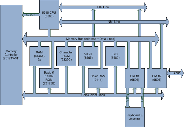
Commodore 64框图(Commodore 64 Block Diagram)
项目结构(Project Structure)
仿真代码被分成几个程序集,因此可以将某些东西(例如CPU,内存和IO端口仿真)重用于其他项目,例如VIC,PET或NES仿真器.(Emulation code is separated in several assemblies so some things, like CPU, memory and IO port emulation, can be reused for other projects like VIC, PET or NES emulators.)
c64_common-时钟,内存,IO端口和中断线仿真(- clock, memory, IO port and interrupt line emulation)c64_cpu-6502和6510仿真(- 6502 and 6510 emulation)c64_av-VIC-II和SID芯片仿真(- VIC-II and SID chips emulation)c64_io-CIA芯片和IEC(串行)总线仿真(- CIA chip and IEC (serial) bus emulation)c64_system-连接所有仿真硬件以及键盘/操纵杆仿真的C64板(- C64 board that connects all emulated hardware as well as keyboard/joystick emulation)c64_1541-1541-II驱动器仿真(- 1541-II drive emulation)c64_environment-模拟器用于与外部世界交互的接口的定义(例如输出图形和音频,读取文件…)(- definition of interfaces used by emulator to interact with external world (like outputting graphic and audio, reading files…))c64_win_gdi-实施GUI并将所有内容连接在一起(C64板,1541-II驱动器和环境)(- implements GUI and connects everything together (C64 board, 1541-II drive and environment))
时钟(Clock)
系统中的所有内容均由CPU时钟同步.时钟周期分为多个阶段.这些阶段定义了每个周期中芯片仿真的顺序,每个芯片占用了周期的一个阶段.在每个相位仿真器中,执行为芯片安排的单个时钟操作.一个周期中可以有任意数量的相位,具体取决于要仿真的芯片数.(Everything in the system is synchronized by the CPU clock. Clock cycles are separated into phases. These phases define the order of chip emulation in each cycle and each chip takes a single phase of the cycle. In each phase emulator execute single clock operation scheduled for the chip. There can be any number of phases in a cycle depending on the number of chips that are emulated.)
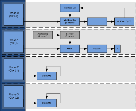
系统时钟框图(System Clock Block Diagram)
ClockOp 定义时钟操作的接口,其中(defines the interface for clock operation where) Execute 应包含应在时钟周期内执行的逻辑.(should contain the logic that should be executed in the clock cycle.)
Clock 类代表系统时钟,它保持应在每个阶段执行的时钟操作队列.(class represent clock of the system, it keeps queue of clock operation that should be executed for each phase.) Clock 不适用于(does not work with) ClockOp 直接但通过(directly but through) ClockEntry 和(and) ClockEntryRep 类.这些类为(classes. These classes provide additional context to) ClockOp 例如应该执行的下一个操作是什么,以及是否应在同一周期内执行该指令.(like what is the next operation that should be executed, and whether that instruction should be executed in same cycle.) ClockEntryRep 该类用于需要多个周期才能完成的操作,并且包含有关其长度(执行周期)的信息.(class is used for operations that take multiple cycles to complete and contains information about its length - number of cycle it takes to execute.)
QueueOpsStart 和(and) QueueOps 方法用于对时钟的指定相位进行排队操作.(methods are used for queuing operations for specified phase of the clock.) QueueOpsStart 对于每个后续请求,在仿真开始后将第一个操作排入队列时使用此方法(method is used when the first operations are queued after the emulation is started, for every subsequent request) QueueOps 应该使用.对于大多数筹码(should be used. For most chips calling) QueueOpsStart 一开始只需要在循环列表中指定所有时钟操作即可.仅CPU正在使用(once at the beginning, with all clock operations specified in cyclic list is usually enough. Only CPU is using) QueueOps 方法对应该在解码指令后执行的操作进行排队.(method to queue operations that should be executed after it decodes the instruction.)
Stall 方法可用于在特定阶段中停止排队操作的执行(即在VIC-II芯片访问RAM时保持CPU)或(methods can be used to stall execution of queued operations in a certain phase (i.e. holding CPU while VIC-II chip is accessing RAM) or) Prolong 如果需要其他周期来完成操作(即执行导致跨页跳转的分支指令).(if additional cycles are required to complete operation (i.e. executing branch instruction that causes cross-page jump).)
一旦一切准备就绪即可开始/恢复仿真,(Once everything is ready to start/resume the emulation,) Run 的方法(method of the) Clock 应该叫.(should be called.) Halt 方法可用于停止执行时钟中排队的操作.这用于在框架完成后,应渲染新帧之前保持仿真,或者用于在驱动器不活动时停止驱动器仿真以节省资源.(method can be used for halting execution of the operations queued in the clock. This is used for holding emulation after the frame is completed and before new one should be rendered, or for stopping drive emulation when drive is not active to save resources.)
当前周期的最后一个阶段完成后,(Once the last phase of the current cycle is completed,) OnPhaseEnd 事件引发.此事件可用于链接其他板卡(如1541-II驱动器)的附加时钟.(event is raised. This event can be used to chain additional clock of other boards like 1541-II drive.)
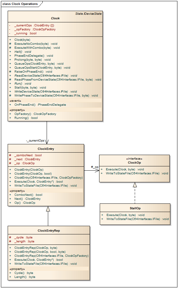
时钟仿真类图(Clock emulation class diagram)
记忆模型(Memory Model)
本章将描述如何实现存储器总线,ROM和RAM的仿真.它还将解释什么是内存映射的设备以及此实现中的内存映射如何工作.(This chapter will describe how the emulation of memory bus, ROM and RAM is implemented. It will also explain what memory mapped devices are and how memory map is working in this implementation.)
内存映射设备(Memory mapped devices)
可以通过内存总线访问的每个设备都是内存映射设备(包括RAM和ROM).它们被映射到由起始地址和大小(存储位置的数量)指定的某个地址范围.(Each device that can be accessed through the memory bus is memory mapped device (including RAM and ROM). They are mapped to a certain address range which is specified by start address and the size (number of memory location).)
MemoryMappedDevice 该类是所有内存映射设备的基础.这些设备应实施并支持(class is base for all memory mapped devices. These devices should implement and support) Read 和(and) Write 当CPU或某些其他芯片使用内存总线读取或写入设备映射到的地址内容时调用的方法.(methods which are called when CPU or some other chip uses memory bus to read or write content of address to which the device is mapped.)
记忆图(Memory map)
内存映射表示内存配置.此配置定义在系统的地址空间中映射哪些设备以及映射它们的位置.需要注意的重要一点是,即使使用相同的内存映射,写入操作也可能触发与读取操作不同的芯片.由于这一要求,此实现有两个单独的映射,一个用于写操作,一个用于读操作.(Memory map represents a memory configuration. This configuration defines which devices are mapped and where they are mapped in the address space of the system. Important thing to notice is that write operations can trigger different chip from read operations for the same memory location even when the same memory map is used. Due to this requirement, this implementation has two separate maps, one for writes, and one for reads.)

内存映射框图(Memory Map Block Diagram)
Commodore 64可以具有程序员可以选择的不同内存映射.为此,仿真器将为每个可能的配置创建多个预先配置的内存映射.(Commodore 64 can have different memory maps that can be selected by the programmer. To accomplish this, emulator will create multiple memory maps are pre-configured for each possible configuration.)
每个位置都由(Each location is represented by) MemoryMapEntry 类,它有两个条目-应该为写入而调用的设备和应为读取而调用的设备.(class and it has two entries - device that should be called for writes and device that should be called for reads.)
MemoryMap 类处理内存映射,它只是内存映射条目的数组.它有(class handles memory mappings and it’s just an array of memory map entries. It has) Map 和(and) Unmap 可以在指定地址空间中映射设备并将其从其中删除的方法.另一对重要的方法是(methods that can map a device in specified address space and remove it from there. Another important pair of methods is) Read 和(and) Write .这些方法将查找哪个设备映射到指定位置以进行请求的内存操作,并在设备上调用适当的方法.(. These methods will find which device is mapped at the specified location for the requested memory operation and invoke appropriate methods on the device.)

内存仿真类图(Memory emulation class diagram)
内存(RAM)
RAM仿真非常简单.内存只是字节数组,可由CPU或其他一些芯片(如VIC-II)读取或写入.(RAM emulation is as simple as it gets. Memory is just an array of bytes which can be read or written to by the CPU or some other chips like VIC-II.)
RAM 类实现RAM的仿真.由于RAM显然已映射到地址空间,因此此类基于(class implements emulation of RAM. Since the RAM is obviously mapped into address space, this class is based on) MemoryMappedDevice 类.(class.) Read 和(and) Write 方法很简单,正如他们所说的那样-读取或写入内存位置.(methods are straightforward and do as they say - read or write memory location.)
只读存储器(ROM)
ROM仿真甚至更简单,实现仅提供读取从预定义文件中加载的字节.(ROM emulation is even simpler, implementation just provide reading of bytes that were loaded from predefined file.)
由于Commodore 64中内存总线的硬件实现,存储到当前映射到ROM的位置将导致将值写入这些位置的RAM.此功能是通过仿真器的内存映射而不是仅忽略写入的ROM仿真来实现的.(Due to hardware implementation of memory bus in Commodore 64, stores to locations which are currently mapped to ROM will result in values being written to RAM at these location. This feature is realized by memory map of the emulator and not by the ROM emulation, which just ignore writes.)
ROM仿真是通过以下方式实现的(ROM emulation is implemented by) ROM 类似于(class which is similar to) RAM 类.它还提供了其他方法(class. It also provides additional method) Patch 允许更改ROM的内容,这对于跳过固件执行的各种检查很有用.(which allows content of ROM to be changed which can be useful for skipping various checks performed by firmware.)
彩色RAM(Color RAM)
Commodore 64具有额外的RAM,专用于存储当前正在显示的所有字符的颜色,VIC-II芯片使用该RAM生成视频输出. VIC-II仅使用每个字节的低4位.(Commodore 64 has additional RAM dedicated for storing colors of all characters that are currently being displayed and it is used by VIC-II chip to generate video output. Only lower 4 bits of each byte is used by VIC-II.)
彩色RAM的仿真在(Emulation of Color RAM is implemented in) ColorRAM 类及其基础(class and it based) RAM 类.(class.)
重影(Shadowing)
在某些情况下,单个设备可以映射到多个位置,但是当前实现不支持此功能.同样,芯片通常会映射到更大的空间,然后才具有寄存器.例如,VIC-II地址大小为1024字节,但只有64个寄存器.在这些情况下,由芯片决定如何对可用寄存器之外的位置进行读/写操作,但是大多数情况下,仅地址的前几位是有效的,而其他的则假定为0.这使内存映射成为可能.看起来这64个寄存器在分配的地址空间中多次映射,以填充整个1024个字节的地址空间.(In some cases, single device can be mapped to multiple locations, but this is not supported by the current implementation. Also chips are usually mapped to much larger space then they have registers. For instance VIC-II address size is 1024 bytes, but it only has 64 registers. In these cases it is up to the chip to determine what it should do with reads/writes to locations beyond available register, but most often only the first few bits of the address are significant and others are assumed to be 0. This makes memory map looks like those 64 registers are mapped multiple times in the allotted address space to fill whole 1024 bytes of address space.)
未映射的地址空间(Unmapped address space)
某些内存配置允许未映射任何设备的地址范围.在实际硬件中,对这些位置的写入将被忽略,而读取将返回预定义的值.在此实现中,将发生异常,这可能会导致某些现有软件出现问题.(Certain memory configurations allow address ranges that do not have any devices mapped. In real hardware, writes to these locations would be ignored and reads would return predefined values. In this implementation an exception would occur, which can cause problems with some of the existing software.)
IO端口(IO ports)
IO端口有多种芯片可用:VIA,CIA和6510 CPU.端口上的引脚可以是输入或输出.引脚的方向可以通过编程控制.这些端口用于连接未直接连接到内存总线的硬件-它们不是内存映射的.这些设备是Commodore 64中的串行总线,键盘和操纵杆,或者1541-II磁盘驱动器中的驱动器头控制器.(IO ports are available in several chips: VIA, CIA and 6510 CPU. Pins on a port can be either input or output. Direction of the pin can be controlled programmatically. These ports are used for connecting hardware that is not connected to memory bus directly - they are not memory mapped. These are devices like serial bus, keyboard and joystick in Commodore 64 or drive head controller in 1541-II disk drive…)
用于控制IO端口的逻辑由(Logic for controlling IO ports is provided by) IOPort 类,因为所有芯片都相同.(class, since it is the same for all chips.)
物产(Properties) Input ,(,) Output 和(and) Direction 提供对IO端口引脚的访问,并允许控制其方向和状态.这些属性会将所有引脚的状态设置为指定值,这并非总是可取的.(provides access to pins of IO port and allows control of their direction as well as their state. These properties will set state of all pins to specified values which is not always desirable.) SetSingleInputFast 当需要更改单个输入引脚的状态时,可以使用此方法.(method can be used when there is a need to change the state of single input pin.)
除了可以读取或设置引脚状态或更改其方向的方法外,此类还可以在输出引脚的状态更改时公开事件-(In addition to methods that can read or set state of pins, or change their direction, this class also exposes event when the state of output pins are changed -) OnPortOut .(.)
这些端口如何控制以及如何暴露给系统的其余部分,取决于它们所属于的芯片逻辑.(How these ports are controlled and exposed to the rest of the system depends on the chip logic of which they are part.)

IOPort类(IOPort class)
中央处理器(CPU)
Commodore 64计算机由MOS6510 CPU驱动.此版本的CPU与MOS6502芯片完全相同,但具有一个额外的通用IO端口,该端口被映射到地址空间.该IO端口用于控制系统的磁带机和内存配置.(Commodore 64 computer is powered by MOS6510 CPU. This version of CPU is exactly the same as MOS6502 chip, but with an extra general purpose IO port that is mapped into address space. This IO port is used for controlling tape drive and memory configuration of the system.)
在仿真器中仅实现记录的操作码.执行非法的操作码(MOS未记录)将导致模拟器崩溃.(Only documented opcodes are implemented in the emulator. Execution of illegal opcodes (not documented by MOS) will cause emulator crash.)
MOS6502 类连接CPU仿真的所有单个组件.(class connects all the individual components of CPU emulation.) MOS6510 类扩展(class extends) MOS6502 并且仅实现该芯片上可用的附加IO端口的仿真.(and it only implements emulation of additional IO port available on that chip.)
CPU寄存器(CPU Registers)
6502具有一组6个寄存器,它们对程序员是可见的.这个集合由(6502 has set of 6 registers that are visible to the programmer. This set is represented by) CPUState 类.(class.)
每个寄存器实现(Each register implements) IRegister 通用接口,其中接口的基础类型取决于寄存器的大小.(generic interface, where the underlying type of the interface depends on the size of the register.)
累加器(A)和索引(X和Y)寄存器通过以下方式实现(Accumulator (A) and index (X and Y) registers are implemented by) GpRegister 类.堆栈寄存器和程序计数器由(class. Stack register and program counter are implemented by) StackRegister 和(and) ProgramCounter 类.(classes, respectively.)
处理器状态寄存器由(Processor status register is implemented by) StatusRegister 每个状态标志作为属性公开的类.(class where each status flag is exposed as property.)
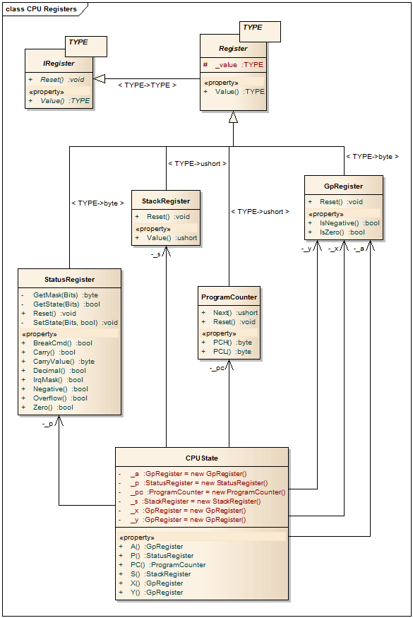
CPU寄存器类图(CPU registers class diagram)
解码(Decoding)
提取和解码操作码是指令执行的第一步.在6502 CPU的情况下,所有操作码都是一个字节长,足以解码整个指令-因此我们知道它是哪条指令以及它使用的寻址方式.(Fetching and decoding opcode is the first step of instruction execution. In case of 6502 CPU all opcodes are one byte long and it is enough to decode whole instruction - so we know which instruction it is and what addressing mode it uses.)
解码过程使用预先创建的查找表,该查找表将操作码映射到结构,该结构指示应调用哪种寻址模式,应执行哪条指令以及它们的时序-寻址,执行和存储结果所需的周期数.该表由(Decoding process uses pre-created lookup table which maps opcodes to structure that indicates which addressing mode should be invoked and which instruction should be executed as well as their timings - number of cycles it takes to address, execute and store result. This table is implemented by) DecodingTable 类.(class.)
然后,解码器将基于从解码表获得的信息创建列表时钟操作,并将其排队等待执行.(Decoder will then create list clock operations that will be queued for the execution based on the information obtained from decoding table.)
解码器本身实现为时钟操作((Decoder itself is implemented as clock operation () DecodeOpcodeOp 类),并将其附加到每个解码指令的时钟操作列表的末尾.(class) and it is attached at the end of clock operation list for every decode instruction.)
编址(Addressing)
指令解码后,下一步是确定操作数.操作数告诉指令的源和/或目的地.(Next step, after the instruction has been decoded, is to determine operands. Operands tell the source and/or destination of the instruction.)
6502/6510 CPU有几种寻址模式,在此不再赘述,因为有关该主题的资料要好得多,包括官方数据表.(6502/6510 CPU has several addressing modes, which are not going to be discussed here, since there are far better sources on the subject, including the official datasheet.)
每种寻址模式都作为单独的类实现,该类实现(Each addressing mode is implemented as separate class which implements) AddressingMode 接口.定义的唯一方法是(interface. The only method defined is) Decode 它负责根据处理器的当前状态计算目标地址.(which is responsible for calculating target address depending on current state of the processor.)

寻址模式的类图(Class diagram of addressing modes)
地址解码过程将根据地址创建并设置CPU的活动目标.目标可以是可写的或仅可读的;它可以是内存或寄存器.目标定义为(Address decoding process will create and set active target of CPU depending on the addressing. Target can be writable or only readable; it can be memory or register. Target is defined by) AddressedTarget 接口,它应该实现用于检索和存储目标位置值的逻辑,并且每种寻址模式都有其自己的种类.(interface it should implement logic for retrieving and storing values of the targeted location and each addressing mode has its own kind.)
ReadableTarget 该类由只需要读取存储器位置的寻址模式使用,而(class is used by the addressing modes that only require reading memory location, while) WritableTarget 此类也需要将值存储到目标位置的那些模式使用class.(class is used by those modes that also requires storing values to the targeted location.) IndirectTarget 寻址模式不直接使用目标地址,而是直接通过另一个存储实际目标位置的中间存储位置来引用目标.(is used by addressing modes which does not reference target directly but through another, intermediate, memory location that stores the actual target location.)
还有一些特定于某些寻址模式的目标,例如以CPU的累加器寄存器为目标的累加器寻址和指定目标为已解码指令一部分的立即寻址.(There are also targets specific for certain addressing modes, like accumulator addressing which targets accumulator register of the CPU and immediate addressing which specify that target is part of decoded instruction.)
重要的是要注意,某些寻址模式要求从程序计数器引用的存储器中获取其他字节以解码目标位置,并且每次获取都会导致将程序计数器移至下一个地址.(It is important to note that some addressing modes require fetching additional bytes from memory referenced by program counter to decode target location and each fetch causes moving program counter to the next address.)

寻址目标的类图(Class diagram of addressing targets)
| 寻址方式(Addressing mode) | 寻址类名(Addressing class name) | 目标类别名称(Target class name) |
|---|---|---|
| Accomulator | AccAddressing |
具体目标((specific target () WritableTarget 作为基础)(as base)) |
| Immediate | ImmAddressing |
具体目标((specific target () ReadableTarget 作为基础)(as base)) |
| Absolute | AbsAddressing |
WritableTarget |
| 零页(Zero Page) | ZeroAddressing |
WritableTarget |
| 索引零页(使用X寄存器)(Indexed Zero Page (using X register)) | ZeroXAddressing |
WritableTarget |
| 索引零页(使用Y寄存器)(Indexed Zero Page (using Y register)) | ZeroYAddressing |
WritableTarget |
| 绝对索引(使用X寄存器)(Index Absolute (using X register)) | AbsXAddressing |
WritableTarget |
| 绝对索引(使用Y寄存器)(Index Absolute (using Y register)) | AbsYAddressing |
WritableTarget |
| Implied | ImpAddressing |
none |
| Relative | RelAddressing |
WritableTarget |
| 索引间接(Indexed Indirect) | IndAddressing |
IndirectTarget |
| 绝对间接(使用X寄存器)(Absolute Indirect(using X register)) | IndXAddressing |
IndirectTarget |
| 绝对间接(使用X寄存器)(Absolute Indirect(using X register)) | IndYAddressing |
IndirectTarget |
地址解码包装(Address decoding is wrapped in) DecodeAddressOp 时钟操作类,因此可以将其排队等待执行.(clock operation class so it can be queued for the execution.)
6502的数据表中描述了每种寻址模式的工作方式.(How each of these addressing modes works is described in 6502’s datasheet.)
使用说明(Instructions)
代表指令的每个类都需要实现(Each class that represents an instruction needs to implement) Instruction 暴露的界面(interface which exposes) Execute 方法.这是负责执行指令逻辑的方法.(method. This is the method which is responsible for executing the logic of the instruction.)
指令的执行阶段被包装到(Execution phase of the instruction is wrapped into) DecodeAddressOp 表示可排队的时钟操作的类.该包装器提供了所有必要的信息,以(class which represent queueable clock operation. This wrapper provides all the necessary information to) Execute 方法,例如执行指令的CPU,占用多个周期的指令所需的当前周期等等.(method, such as CPU that executes the instruction, current cycle needed for instruction that take multiple cycles and so on…)
中断(Interrupts)
6502/6510 CPU有两条中断线-标准中断线可屏蔽(IRQ)和不可屏蔽(NMI). IRQ线是电平触发的-意味着CPU在每次电平升高时都会检测到中断,而NMI线是边沿触发的-意味着CPU仅在该线的电平从低变高时才能识别.(6502/6510 CPUs have two interrupt lines - standard one that is maskable (IRQ) and non-maskable (NMI). IRQ line is level triggered - meaning that CPU will detect interrupt every time the level of the line is raised, while the NMI line is edge triggered - meaning the CPU will recognize only when the level of the line changed from low to high.)
中断线仿真是通过(Interrupt line emulation is realized by) IrqLine 和(and) NmiLine 类.不幸(classes. Unfortunately) NmiLine 无法正确处理多个中断源.(does not handle multiple interrupt sources correctly.)
CPU是这些行的所有者,但是连接到它们的芯片可以获取引用,并使用它们来提高或降低该行的级别.(CPU is the owner of these lines, but chips that are attached to them can get the references and use them to raise or lower the levels of the line.)
负责指令解码的时钟操作((Clock operation that is responsible for instruction decoding () DecodeOpcodeOp )在获取下一条指令之前检查中断线.如果任何一条线是活动的,它将排队负责中断处理的时钟操作.对于可屏蔽中断(IRQ),此操作将在开始中断处理之前检查进程状态寄存器.() checks interrupt lines before it fetches the next instruction. If any of the lines are active it will enqueue clock operation that is responsible for interrupt handling. In the case of maskable interrupt (IRQ) this operation will check process status register before it starts interrupt handling.)
中断处理时钟的操作由(Interrupt handling clock operation is implemented by) InterruptOp 类.(class.)

CPU不同时钟操作的类图(Class diagram of CPU’s different clock operations)
6510 IO端口(6510 IO port)
6510唯一的附加功能是IO端口.端口始终映射到地址(The only addition to 6510 is IO port. The port is always mapped to addresses) $0000 (引脚方向寄存器)和((pin direction register) and) $0001 (引脚状态寄存器).参考中提供了每个引脚的确切功能.((pin state register). Exact function of each pin is provided in the references.)

MOS 6502/6510仿真类图(MOS 6502/6510 emulation Class diagram)
准将64(Commodore 64)
下一节讨论Commodore 64主板上存在的单个芯片和硬件组件的仿真.(The following section discusses emulation of individual chips and hardware components that are present on Commodore 64’s main board.)
VIC-II芯片(VIC-II chip)
该芯片负责在Commodore 64中生成图形.尽管没有VIC-II芯片的正式数据表,但有一篇文章详细介绍了该芯片的内部工作原理,这是反向工程的产物.本节的链接提供了参考.对于读者来说,在深入了解实际实现的细节之前最好先熟悉一下该主题.(This chip is responsible for generating graphic in Commodore 64. Although there is no official datasheet for VIC-II chip, there is an article with the detailed description of internal workings of the chip which is a product of reverse engineering. Link to the article is provided in the section with references. It would be good for a reader to get familiar with the subject before getting into details of the actual implementation.)
VIC-II仿真由(VIC-II emulation is implemented by) VIC 类.由于芯片被映射到地址空间并通过内存总线进行访问,(class. Since the chips is mapped in address space and accessed through the memory bus,) VIC 上课要延长(class have to extend) MemoryMappedDevice .(.) Read 和(and) Write 方法负责检索芯片寄存器的状态并进行更新.(methods are responsible for retrieving state of chip’s register and updating them.)
RasterLine 类负责管理每个周期中芯片执行的明确定义的操作序列.(class is responsible for managing the well-defined sequence of operations performed by the chip in each cycle.)
每个时钟周期分为两个步骤-内存访问操作和图形生成操作.有些周期定义了两个操作,另一些则只有一个或没有.为了涵盖所有情况,VIC-II芯片有几种实现时钟操作的方法:(Each clock cycle is separated in two steps - memory access operation and graphic generation operation. Some cycles have both operations defined, others have only one or none. To cover all the cases there are several implementations clock operations for VIC-II chip:)
VicNop-整个芯片处于空闲状态的周期(- cycles where the whole chip is idle)VicGraphOp-仅图形生成器处于活动状态,但芯片不需要内存访问的循环(- cycles where only the graphic generator is active, but no memory access is needed by the chip)VicReadOp-图形生成器处于空闲状态,但芯片需要内存访问的循环(- cycles where graphic generator is idle, but the memory access is required by the chip)VicGraphReadOp-需要内存访问并激活图形生成器的循环(- cycles that requires memory access and have graphic generator active)VicReadOp62-的特殊情况(- special case of)VicReadOp仅用于栅格线的最后一个周期(which used only for the last cycle of raster line) 栅格行具有两个预定义的时钟操作列表.一个列表表示当图形输出处于活动状态时应在光栅行中执行的操作,而另一个列表包含在图形输出处于空闲状态时(由渲染边框或由程序员以编程方式禁用)由VIC-II芯片执行的操作.(Raster line has two pre-defined lists of clock operations. One list represents operations that should be performed in the raster line when graphic output is active and the other list contains operations that are performed by VIC-II chip when graphic output is idle - during rendering borders or deactivated programmatically by the programmer.)
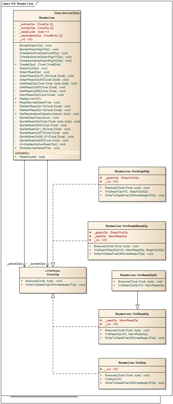
栅格线仿真类图(Raster line emulation class diagram)
如前所述,每个循环都有严格定义的一组动作.用于内存访问和图形生成器操作的每个周期的逻辑被实现为不同的方法(As it already mentioned, each cycle has strictly defined set of actions that it performs. Logic of each cycle for memory access and graphic generator operations are implemented as different methods of) RasterLine 类.这些方法负责更新芯片的状态,执行内存读取并调用活动图形模式以生成图形.(class. These methods are responsible for updating state of the chip, performing memory reads and invoking active graphic mode to generate graphic.)
图形模式负责生成除精灵图形外的所有图形输出.每个图形模式都有自己的实现类(Graphic modes are responsible for generating all graphic output except sprite graphic. Each graphic mode has its own class that implemented) GraphiceMode 接口.界面的唯一方法是渲染,它将根据芯片的当前状态为当前位置生成像素.(interface. The only method of the interface is render, which would generate pixel for the current position according to current state of the chip.)
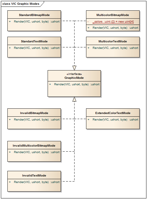
VIC-II图形模式的类图(Class diagram of VIC-II’s graphic modes)
RasterLine 类还负责为精灵生成图形输出.(class is also responsible for generating graphic output for sprites.)
Output 的方法(method of) IVideoOutput 当芯片需要在屏幕上输出像素时,调用接口.(interface is called when the chip needs to output pixel on the screen.)
VIC-II对象还保留碰撞矩阵以实现芯片的碰撞检测功能.该矩阵存储每个像素的信息,并定义该像素是否会引起与另一个精灵的碰撞.该信息在输出背景图形的像素时存储,并在输出精灵图形时进行检查.(VIC-II object also keeps collision matrix to implement collision detection feature of the chip. This matrix stores information for each pixel and it defines whether the pixel can cause collision with another sprite or not. This information is stored when pixel of background graphic is outputted and checked when sprite graphic is outputted.)

VIC-II芯片仿真类图(VIC-II chip emulation class diagram)
CIA芯片(CIA chip)
CIA芯片具有两个IO端口(A和B),两个计时器(A和B),一个时钟(Time of Day或TOD)和串行引脚(在Commodore 64中未使用).这些芯片负责与IO设备的连接,例如直接连接的键盘和操纵杆以及通过IEC总线的磁盘驱动器和打印机.(CIA chip has two IO ports (A and B), two timers (A and B), one clock (Time of Day or TOD) and serial pin which is unused in Commodore 64. These chips are responsible for connectivity with IO devices such as keyboard and joysticks that are connected directly and disk drives and printers that are through IEC bus.)
芯片连接到中断线,因此它们可以在需要时引发中断,即,当输入引脚的状态改变,计时器达到0等时.CIA#1连接到IRQ线,而CIA#2连接到NMI线,但是在此实现中,它还错误地连接到IRQ线路.(The chips are attached to interrupt lines so they can raise interrupts when required, i.e. when the state of input pin is changed, timer reached 0, etc. CIA #1 is attached to IRQ line while CIA #2 is attached to NMI line, but in this implementation it is also attached to IRQ line incorrectly.)
两个CIA都映射到Commodore 64的地址空间中,因此可以通过内存总线对其进行访问.(Both CIAs are mapped into address space of Commodore 64, so they can be accessed through memory bus.)
有关CIA芯片每个组件的详细信息,您可以在参考文献中找到CIA数据表的链接.(For the details about each component of CIA chip you can find link to CIA datasheet in the references.)
芯片的仿真是通过以下方式实现的(Emulation of the chip is implemented by) CIA 类.本课延伸(class. This class extends) MemmoryMappedDevice 因为CIA被映射到内存空间.(since CIAs are mapped into memory space.) Read 和(and) Write 方法读取并更新芯片的寄存器.(method reads and updates registers of the chip.)
CIA 类也实现(class also implements) ClockOp 负责更新计时器计数器的接口.在某些情况下,当重新加载计时器时,CIA芯片将空闲几个周期,但此实现未将其覆盖.(interface which is responsible for updating timers' counters. In some cases CIA chip will be idle for a few cycles when the timer is reloaded, but they are not covered by this implementation.)
计时器仿真是通过以下方式实现的(Timer emulation is implemented by) TimerState 类.(class.)
IncrementTod 在每一帧结束后调用负责更新每日时间的方法.(method which is responsible for updating Time of Day is called after end of each frame.)
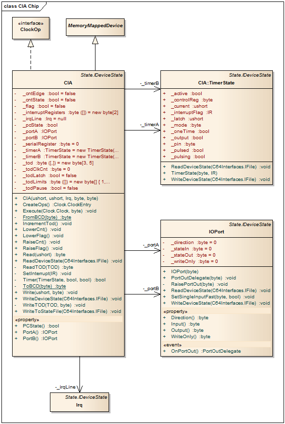
CIA芯片仿真类图(CIA chip emulation class diagram)
SID芯片(SID chip)
不幸的是,没有实现SID芯片仿真,因此这里不再讨论.本文的参考部分提供了SID数据表的链接.(SID chip emulation is not implemented, unfortunately, and it will not be discussed here. Link to SID datasheet is provided in the reference section of the article.)
内存配置(Memory Configurations)
Commodore 64具有几种内存配置,可以通过设置6510的IO端口的前3位来选择适当的配置.有关每种配置的详细信息,请参见参考文章.每个配置(可能有8种)都有自己的实例(Commodore 64 has several memory configurations and appropriate configuration can be selected by setting the first 3 bits of 6510’s IO port. Details about each configuration can be found in referenced articles. Each configuration, of 8 possible, has its own instance of) MemoryMap 在启动时已预先配置.由于足以设置对适当实例的引用,因此可以提高性能(which is pre-configured at the startup. This improves performance since it is enough to set reference to appropriate instance of) MemoryMap 通过写入IO端口更改内存配置时.(when the memory configuration is changed by writing the IO port.)
键盘和操纵杆(Keyboard and Joystick)
在Commodore 64中,键盘和操纵杆连接到CIA#1芯片的IO端口(A和B).键盘形成一个矩阵,可以根据输出端口A和输入端口B的状态进行解码.(In Commodore 64, keyboard and joysticks are connected to IO ports (A and B) of CIA #1 chip. Keyboard forms a matrix which can be decoded based on state of output port A and input port B.)**恢复(Restore)**直接连接到NMI线(未实现).(is attached directly to NMI line (this is not implemented).) Keyboard class负责从系统接收按键,根据矩阵和输出端口A进行转换,并设置输入端口B的状态.(class is responsible for receiving key presses from the system, converting them according to the matrix and the output port A and setting the state of input port B.)
IEC总线(IEC bus)
IEC总线用于与磁盘驱动器(例如1541-II)和打印机进行通信.它具有三行:DATA,CLOCK和ATN.这些线路连接到CIA#2的IO端口B.即使CIA芯片具有串行通信的硬件支持,也不会使用此功能,但是该协议是通过软件实现的.(IEC bus is used for communication with disk drives, such as 1541-II, and printers, among the other things. It has three lines: DATA, CLOCK and ATN. These lines are attached to IO port B of CIA #2. Even though CIA chip has hardware support for serial communication, this feature is not used, but the protocol is implemented in software.) SerialPort 该类实现串行总线仿真,其中每行由(class implements serial bus emulation, where each line is represented by) BusLine 类.线的状态可以用(class. State of the line can be controlled with) State 的财产(property of) BusLine 类.该类跟踪使线路保持低电平的设备数量,并在线路状态更改时引发事件.设备不是直接连接到生产线上,而是通过(class. The class tracks how many devices keeps the line low and raises an event when the state of the line is changed. Devices are not attached to the line directly but through and object of) BusLineConnection 负责跟踪本地状态的类-该设备设置的线路状态.(class which is responsible for tracking local state - state of the line set by that device.)

IEC总线仿真类图(IEC bus emulation class diagram)
1541-II驱动器(1541-II Drive)
该仿真器还实现了1541-II磁盘驱动器的真实驱动器仿真.这意味着仿真不在IEC总线协议级别上,而是对驱动器的实际硬件进行了仿真.这种类型的仿真需要更多资源,但提供了更好的兼容性.(The emulator also implements real drive emulation of 1541-II disk drive. This means that emulation is not on IEC bus protocol level but that the real hardware of the drive is emulated. This type of emulation requires more resources, but provides much better compatibility.)
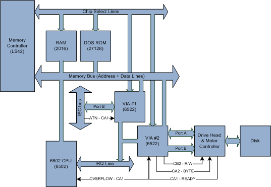
1541-II驱动框图(1541-II drive block diagram)
GCR编码和D64格式(GCR Coding and D64 Format)
GCR是Commodore用来在磁盘上存储信息的格式.它定义了数据在磁盘上的放置方式:磁道大小,数据同步,扇区头的外观以及扇区数据的编码.带有参考的部分中提供了包含格式详细说明的链接.(GCR is format used by Commodore to store information on disks. It defines how the data are laid on disk: track sizes, data synchronization, how sector headers looks like and coding of sector data. Link that contains detailed explanation of the format is provided in sections with references.)
用于存储磁盘映像的最广泛的格式是D64,因此它是此处唯一实现的格式. D64格式的磁盘映像包含来自实际磁盘的扇区数据.这些是Commodore 64从磁盘驱动器接收的扇区数据,并且未经GCR编码.除扇区数据外,还有D64格式的版本可提供用于模拟坏扇区的其他数据,从而提高了与某些版权保护机制的兼容性.不幸的是,这里没有实现这些扩展. D64格式也包含在参考资料中.(The most widespread format for storing disk images is D64, so it is the only one implemented here. Disk images in D64 format contains sector data from actual disk. These are the sector data that Commodore 64 receives from the disk drive and they are not GCR encoded. In addition to sector data, there are versions of D64 format that provide additional data for emulation of bad sectors, which improves compatibility with some copyright protection mechanisms. Unfortunately these extensions are not implemented here. D64 format is also covered by the referenced material.)
GCRImage class负责从D64格式加载磁盘映像,并创建内存中GCR编码的映像,其余的1541-II仿真器都可以使用.(class is responsible for loading disk images, from D64 format, and creating in-memory GCR encoded image that can be used by the rest of 1541-II emulator.)

GCRImage类(GCRImage class)
威盛芯片(VIA chip)
像它的后继产品CIA芯片一样,VIA是IO端口控制器.它提供了两个通用IO端口以及两个可编程定时器.除了8个IO引脚外,每个端口还有两条额外的控制线,可用作中断输入或握手输出.(VIA is an IO port controller like its successor - CIA chip. It provides two general purpose IO ports as well as two programmable timers. In addition to 8 IO pins each port has two additional control lines that can be used as interrupt inputs or as handshake outputs.)
驱动器磁头和电动机以及IEC总线线路连接到驱动器中安装的两个VIA芯片的端口.(Drive head and motor as well as the IEC bus lines are attached to the ports of two VIA chips that are installed in the drive.)
VIA 类实现芯片的仿真.它延伸(class implements emulation of the chip. It extends) MemmoryMappedDevice 因为VIA映射到驱动器CPU的内存空间.(since VIAs are mapped into memory space of the drive’s CPU.) Read 和(and) Write 方法读取并更新芯片的寄存器.(method reads and updates registers of the chip.)
该类还实现(This class also implements) ClockOp 该接口负责更新计时器的计数器以及端口的控制线.(interface which is responsible for updating timers' counters as well as ports' control lines.)
PortA 和(and) PortB 该类的属性公开了VIA芯片的两个IO端口.(properties of the class expose two IO ports of VIA chip.) CA1 ,(,) CA2 ,(,) CB1 和(and) CB2 属性提供对IO端口控制线的访问.(properties provide access to control line of the IO ports.)

威盛和驱动器磁头仿真类图(VIA and Drive head emulation class diagram)
驱动头(Drive head)
驱动器磁头是机电子系统,它控制驱动器的电机,磁头的位置以及从磁盘读取数据/向磁盘写入数据的磁头本身.它连接到IO端口VIA#2,其中端口B负责头控制,端口A负责传输数据.(Drive head is electro-mechanical subsystem that controls drive’s motors, position of the head and the head itself that reads/writes data from/to the disk. It is attached to IO ports VIA#2, where port B is responsible for head control and port A is responsible for transferring data.)
磁头还连接到VIA芯片的控制线以及CPU的SO引脚,该引脚设置溢出标志,以通知其数据已准备好读取或已被写入磁盘.(Head is also attached to control lines of VIA chip as well as SO pin of CPU, which sets overflow flag, to notify it that the data are ready for reading or that they have been written to disk.)
DriveHead 顾名思义,class实现了驱动器头部的仿真.该类实现(class as its name suggests implements emulation of drive’s head. This class implements) ClockOp 接口,因此将在每个时钟周期执行用于读取或写入数据的逻辑.如果磁头处于活动状态(由VIA芯片控制),则在经过一定次数的循环后,数据将变为可用于读取操作或存储到磁盘以进行写入操作.为了增加磁盘的容量,磁道具有不同的密度,具体取决于磁道距磁盘中心的距离.因此,待完成的读/写操作将要完成的周期数取决于磁头所在的当前磁盘磁道.(interface, so in each clock cycle logic for reading or writing data will be executed. If the head is active, which is controlled by the VIA chip, after certain number of cycles, data will become available for reading operation or stored to disk for write operation. To increase capacity of disks, tracks have different density, depending how far away they are from the center of the disk. So the number of cycles after which the pending read/write operation will be completed depends on the current disk track on which the head is positioned.)
持续的仿真器状态(Persisting Emulator State)
每个仿真的设备都有特定的状态,如果我们希望能够保存或加载仿真会话,则这些状态应保存在文件中,这是仿真器的非常有用的功能,并且可以简化旧游戏.(Each emulated device has certain state, these states should be persisted in a file if we want to be able to save or load emulation session which is very useful feature of an emulator and makes old games much easier.)
仿真器仅在发出保存命令的帧的末尾保存状态.这样做的原因是简化了负责处理VIC-II芯片状态的代码.(Emulator will save state only at the end of a frame during which the save command is issued. The reason for this is simplification of code that is responsible for handling the state of VIC-II chip.)
仿真器的保存和加载状态通过以下方式完成(Saving and loading state of the emulator is done through) IDeviceState 接口.需要保存其状态的每个模拟组件的类都应实现此接口.(interface. Class for each emulated component that needs to save its state should implement this interface.) ReadDeviceState 和(and) WriteDeviceState 当状态需要保留或恢复时,将调用接口的方法.仿真组件可以使用对文件对象的引用来读取或写入状态文件,这是这两种方法的参数.(methods of the interface are called when state needs be persisted or restored. Emulated component can read or write state file using reference to file object that is provided as a parameter of these two methods.)
如果是复合的并且包含其他实现的组件(If it is composite and contains other components that implement) IDeviceState 接口,父组件应在其所有子组件上调用适当的方法.例如,C64开发板将在代表内存,CPU和所有其他芯片的组件上调用存储/加载方法.(interface, parent component should call appropriate methods on all of its subcomponents. For instance, C64 board will call store/load methods on components that represent memory, CPU and all other chips.)

IDeviceState接口(IDeviceState interface)

仿真器状态的结构(Structure of Emulator State)
环境(Environment)
环境项目包含旨在将外部系统与仿真器隔离的接口.当前定义了两个接口:(Environment project contains interfaces whose purpose is to isolate external system from the emulator. Currently there are two interfaces defined:) IVideoOutput 提取视频输出的接口,以及(interface which abstracts video output and) IFile 提取文件操作.(which abstracts file operations.)
ROM文件(ROM Files)
由于法律原因,ROM文件未包含在源代码中,但应在Internet上提供它们:(ROM files are not included in source code, due to legal reasons, but they should be available on the Internet:)
模拟器所需的文件是:(Files that are required by the emulator are:)
kernal.rom-ROM芯片托管OS的内容(- content of ROM chip hosting OS)basic.rom-ROM芯片托管基本解释器的内容(- content of ROM chip hosting Basic interpreter)chargen.rom-字符ROM(- Charachter ROM)d1541.rom-CBM 1541-II驱动器的固件(- firmware of CBM 1541-II drive) 它们应该复制到(They should be copied to).\c64_roms项目的文件夹.如果只是尝试运行仿真器二进制文件,则将ROM文件复制到可执行文件所在的文件夹中.(folder of the project. If you are just try to run the emulator binaries, copy ROM files into the same folder with the executables.)
参考文献(References)
本节提供了有关硬件的官方文档和数据表的链接.它还链接到非常有用的资源,这些资源是Commodore 64的硬件和软件的反向工程产品,例如内存映射,非法操作码,ROM拆卸等.(This section provides links official documentation and datasheets for hardware. It also has links to very useful resources that are product of reverse engineering of Commodore 64’s hardware and software, such as memory maps, illegal opcodes, ROM disassemblies…)
硬件数据表和文档(Hardware datasheets and documentation)
- MOS 6510数据表-CPU [(MOS 6510 Datasheet - CPU [) PDF格式(PDF) ](])
- MOS 6502非法操作码-CPU [(MOS 6502 Illegal Opcodes - CPU [) 文本(TXT) ](])
- MOS 6526数据表-CIA [(MOS 6526 Datasheet - CIA [) PDF格式(PDF) ](])
- MOS 6522数据表-VIA [(MOS 6522 Datasheet - VIA [) PDF格式(PDF) ](])
- MOS 6581数据表-SID [(MOS 6581 Datasheet - SID [) PDF格式(PDF) ](])
- MOS 6567说明-(VIC-II)[(MOS 6567 Description - (VIC-II) [) 文本(TXT) ](])
内存映射(Memory Maps)
- C64内存映射[(C64 Memory Map [) 的HTML(HTML) ](])
- CMB 1541-II驱动器内存映射[(CMB 1541-II Drive Memory Map [) 的HTML(HTML) ](])
ROM分解(ROM Dissasemblies)
- 基本和核心ROM拆卸[(BASIC and KERNAL ROMs Disassemblies [) 的HTML(HTML) ](])
- CBM 1541-II固件拆卸(DOS 2.6 ROM)[(CBM 1541-II Firmware Disassembly (DOS 2.6 ROM) [) 的HTML(HTML) ](])
硬件原理图(Hardware Schematics)
- C64原理图[(C64 Schematics [) GIF(GIF) ,(,) GIF(GIF) ](])
- CMB 1541-II驱动器原理图[(CMB 1541-II Drive Schematics [) PNG(PNG) ](])
其他(Others)
- D64文件格式[(D64 file format [) 文本(TXT) ](])
- IEC总线[(IEC bus [) PDF格式(PDF) ](])
- 来源文章(Original article)
历史(History)
- 2014年7月23日-原始文章(23 July 2014 - Original Article)
- 2014年7月28日-添加了有关1541-II驱动器仿真的信息(28 July 2014 - Added information about 1541-II drive emulation)
许可
本文以及所有相关的源代码和文件均已获得The Code Project Open License (CPOL)的许可。
C# VS2010 Visual-Studio 新闻 翻译